
Introduction
This guide reveals instructions on how to install a 997, Boxster, & Cayman Radio professionally.
Vehicles with Bose Amplifier will require a HUR Unit to interface the existing Bose Amplifier.
BOSE Subwoofer can be controlled independently using the CAI-Store Bose subwoofer retention connection... this is optional and only offers more control of the subwoofer.
CAI-Store.com sells the head unit and HUR pre wired and programed.
Please visit their site to purchase the radio and HUR unit.
-
-
There is a single Torx screw hidden in the carpeted side panels on either side of the console under the dash area that needs to be removed in order to remove the small carpeted panels.
-
Once this panel has been removed you will have access to the two Torx screws that hold the console side panels on. If you have a Bose equipped Cayman or 911 Cabriolet, you will need to remove the subwoofer on the passengers side of the console before the two console side covers will be accessible.
-
If your vehicle does not have the passenger side subwoofer you cam skip the following sequence and jump right to "Remove the Console Side Covers" below.
-
-
-
This step only applies to vehicles with a Bose Subwoofer in the passenger footwell.
-
Remove the plastic center cover from the air vent. It simply pulls off. This will expose a single Torx screw.
-
Now remove the large Torx screw that fastens the subwoofer to the console.
-
Pull rearwards on the subwoofer enclosure. The whole assembly will now be free. Unplug the subwoofer harness and remove from the vehicle.
-
-
-
Bose equipped vehicles have a subwoofer with an internal amplifier. This amplifier can be made to work with your new aftermarket radio's subwoofer output (RCA) by adding an optional signal harness. This harness will send both audio signal as well as a turn on trigger signal to the subwoofers internal amplifier.
-
The subwoofer will operate as the manufacture intended without the special harness.
-
The subwoofer level control on the radio will not effect the subwoofer output. The advantage of using the optional subwoofer harness is that you will have full control of the subwoofer output relitave to the main volume. Use this feature to make the audio system sound more or less aggressive.
-
-
-
Note: The connections described bellow show how the connections are made directly at the subwoofer in a Cabriolet or Cayman with the subwoofer on the passenger side of the console. The same wires can also be found at the main amplifier in the trunk of '05-'08 vehicles and at the main amplifier under the passengers side seat in '09-''12 vehicles.
-
The subwoofer signal travels from the main amplifier out to the subwoofer. Not from the radio to the subwoofer. The only reason why you would want to make these connections directly at the subwoofer in a Cayman or Cabriolet is because the subwoofer has to be pulled out to gain access to the radio anyway.
-
In a 911 coupe it makes sense to make these connections at the main amplifier in stead of at the subwoofer because the subwoofer is located all of the way at the rear of the car.
-
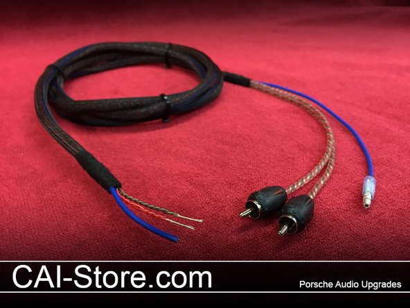
The harness has RCAs and a bullet connector on one end. This end will connect to your new radio. Connect the RCAs to the subwoofer outputs. Connect the Blue wire with the bullet connector to your radios Blue/White remote output wire.
-
The other end of this harness has three wires: Blue - Remote out, Red - Audio signal + and the Brown - Audio signal -.
-
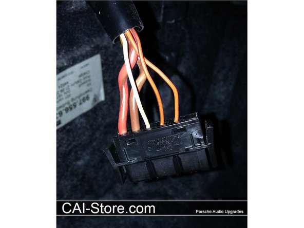
The factory subwoofer harness has 5 wires in it. The large gauge Red/Brown wire is 12 votls power. Leave this wire as is. The large Brown wire is 12 ground. Leave this wire as is. The White/Yellow wire is a 12 volt remote turn-on trigger wire.
-
Cut this wire and permanently insulate the side that leads back to the vehicle. Connect the Blue wire from the subwoofer retention harness to this White/Yellow wire leading to the subwoofer. The two remaining wires are Orange and Orange/Brown. These are the audio signal wires.
-
Cut and permanently insulate the side leading back to the vehicle. Connect the Orange/Brown wire (audio -) to the Brown wire of the subwoofer retention harness. Connect the Orange wire (Audio +) to the Red wire on the subwoofer retention harness.
-
-
-
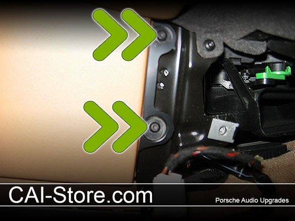
Remove the two Torx screws at the rear of each panel. Passenger side shown below.
-
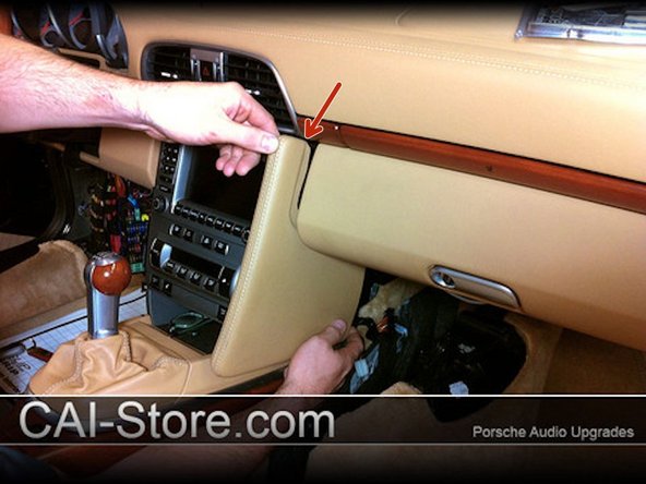
Pull each side cover towards the rear of the car.
-
The Arrow shows the location of a very delicate clip. Be cautious not to break it.
-
On the passenger side the top corner of the panel likes to stay in place. Pull strait out firmly and the panel will release.
-
-
-
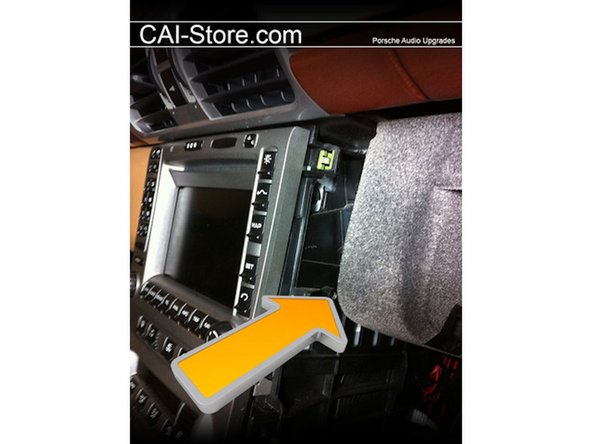
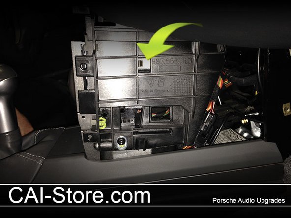
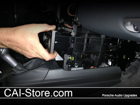
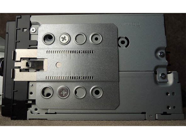
On the passenger side of the radio there is a single 7 mm screw that must be loosened before the radio will come out. The screw head is very close to the glovebox. An open ended or ratcheting combination wrench is required to remove.
-
Once removed, this screw is no longer needed and can be left out if you choose. The picture below shows the screw location with the screw removed.
-
-
-
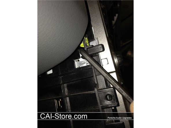
There are 2 retaining clips on each side of the radio chassis (4 total). These clips are locked or unlocked by rotating a plastic 5 mm Allen on each clip. Use an "L" shaped Allen wrench and turn 1/4 counter clockwise to release each retaining clip.
-
Warning If you turn too far, or the wrong way, you can break the release mechanism.
-
In the event one or more breaks, you can simply use a flat blade screwdriver to push the retaining clip towards the radio to release the radio.
-
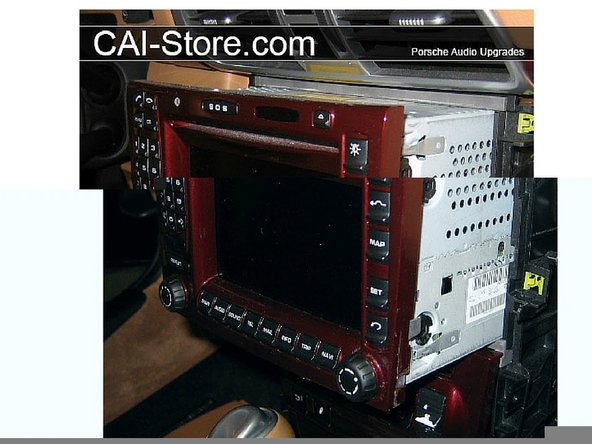
When pulling the radio out and unplugging everything, be careful not to kink the orange fiber optic cables. Once the radio is out you will see a flat plastic wire retainer that is used to organize the cables behind the radio. Remove this retainer, as it will only get in your way when putting the new radio back in place.
-
Once the plastic retainer is removed, tuck any unused plugs way back and out of the way. You want to make as much room as possible. you will notice that there are two antenna leads. One is Black and one is Yellow. You won't be using the Yellow lead. Separate it from the other wires and permanently tuck it out of the way.
-
-
-
Remove the climate controls. To do this, simply locate the metal spring loaded tabs on either side of the climate control and press them in with your finger tips while pulling the climate control unit out towards yourself. Unplug and set aside. Tip: cover your center console and shifter with a towel to avoid scratches.
-
There are a few connections that need to be made outside of the radio cavity. To simplify installation we have found the easiest and most centralized locations to find these circuits in the vehicle.
-
Kenwood radios will require: Accessory, Illumination. Note: some Kenwood units have an auto dim feature. If this feature is enabled then this connection is not required and the Parking Brake.
-
Alpine radios will require: Accessory, Illumination. Parking Brake and the Foot Brake.
-
Alpine radios require connection to the vehicles foot brake and that Kenwoods do not. This connection is necessary for Alpine radios. If this connection is not made the radio will not allow several functions to operate properly.
-
Alpine Radios have an optional VSS (vehicle Speed Sense) connection. This connection allows the navigation to continue tracking the vehicles location in areas where the GPS will not work (long tunnels). This connection is not required for good performance under normal conditions.
-
Note: All circuits should be tested with a digital multimeter to verify identity before connection. Do not make any connection to the vehicle without testing properly. Damage may result. If in any doubt, consult with a qualified professional.
-
-
-
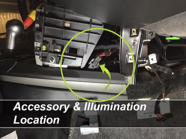
Behind the center console structure (not inside the radio cavity). This location Is the Recommended Connection Point
-
Please See Wiring Color Document at beginning of guide
-
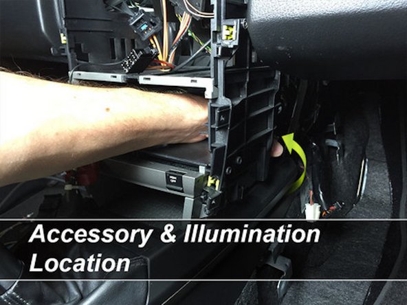
This connector contains both Acessory (Orange) and Illumination (Grey/Red) circuits. The plug is in a hard to reach spot. To make things easier, remove the HVAC controls by pushing in on the metal side tabs and then pulling the control box out from the front. Unplug and set aside.
-
Release the black plug from it's mounting bracket by turning it counter clockwise and pulling it off of the bracket. Once off of the bracket, unplug the two sides of the harness. This is most easily done by putting one hand through the HVAC opening and grabbing the other side of the plug through the side opening.
-
-
-
Remove the small panel below the emergency brake. A hook tool makes this easy. The panel lifts up from the rear.
-
Under this panel you will find a wire harness that has three of the circuits that you will need to tap into. A hook tool comes in very handy to pull the wires up to a point where the can be accessed (don't force them).
-
Please Reference wiring color guide document at beginning of guide.
-
-
-
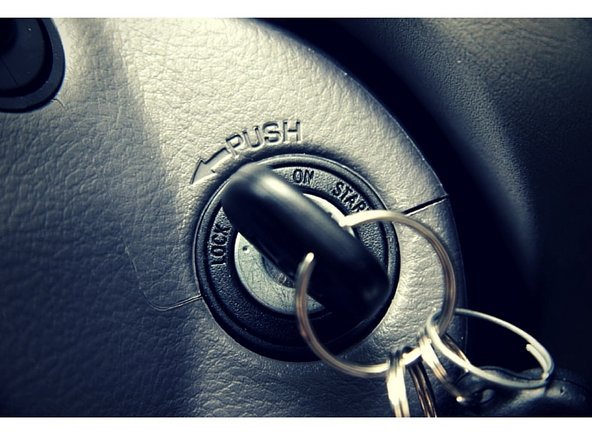
This circuit will supply 12 volts when the key is placed in the ignition switch. This wire is Orange in color. There should be only one of these located under the hand brake lever. Once identified, test to verify that this is indeed the correct wire.
-
To test this circuit, ground the negative side of your multimeter and probe wire with the positive side of your meter. This wire should not show 12 volts with the key out of the ignition switch. Once you have positively identified the correct wire, use the supplied wire tap to make your connection.
-
Illumination: This circuit will supply 12 volts only when the parking lights are turned on. The wire is Grey with a Red stripe. There are two wires in this area of the car that are the same size and color. Only one is the correct wire. Test to verify.
-
Ground the negative side of your meter and probe the suspected wire with the positive lead of your meter. Turn headlights on and off to verify operation.
-
Once you have positively identified the correct wire, use the supplied wire tap to make your connection.
-
Parking Brake: This circuit will supply a connection to ground when the vehicles parking brake is engaged. The wire color is Yellow. It is paired with a Grey/Brown wire and is located just rear of the other two connections that you just made for accessory and illumination.
-
Once you have positively identified the correct wire, use the supplied wire tap to make your connection. That is all of the connections that need to be hardwired to the vehicle. All other connections are plug and play with the supplied harnesses.
-
Foot Brake (Alpine Only): Alpine radios require connection to the cars foot brake to establish that the car is parked and not in moving. The circuit will supply radio with 12 volts when the cars brake pedal is pressed. Wire color is Black with a Yellow stripe. The wire will show 12 volts when the ignition is on. It's at the brake pedal switch.
-
-
-
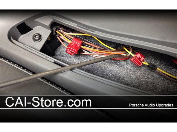
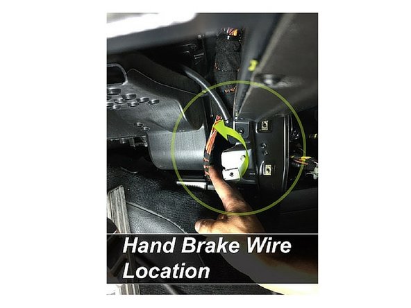
On the left hand side of the console you can also access the hand brake wire on most cars. This will be a yellow wire that will show continuity with vehicle ground when the parking brake is engaged. Test before connecting.
-
Note: on some cars this wire is not easily accessible at this location. In other cars this wire is very easily found here. For the not so easy vehicles the connection should be made below the hand brake.
-
Note: on some vehicles the Yellow hand brake wire will have a colored stripe. To confirm the hand brake wire color, pull the access plate below the hand brake lever and check the actual wire color visually.
-
-
-
Assemble the dash kit side brackets as shown in the picture below. The right angle stops should be flush with the front of the radio chassis (not the face).
-
Insert the mounting cage into the radio cavity. Use the mounting cage that came with the dash kit instead of the mounting cage that came with your radio.
-
-
-
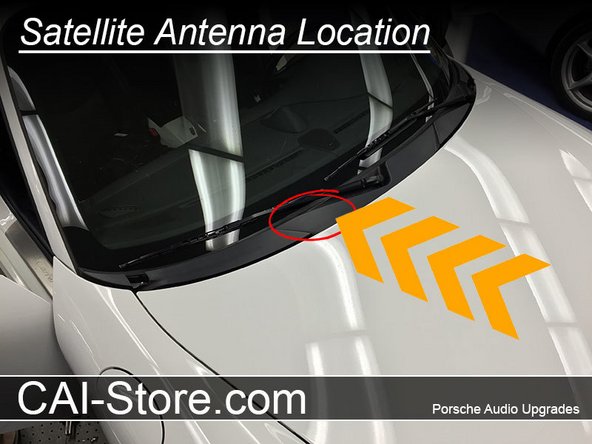
GPS Antenna: There are two good locations for the GPS antenna. Ideally the antenna should have a clear view of the sky with no metal obstructions. Plastic and glass do not pose a problem.
-
Location #1: We offer a premium satellite antenna mount that gets installed under the windshield wiper cowling. This plastic panel bridges the gap between the windshield and the hood. in this location the antenna is not visible from the outside of the vehicle and is not subjected to the elements.
-
There is a flat area of steel next to the cabin filter in the battery compartment where the antenna mount can be installed. Click here to read the full set of instructions for our Premium Satellite Antenna Mount.
-


Cancel: I did not complete this guide.
One other person completed this guide.